WEGO + DynoJet + SuperFlow Tech Info
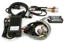


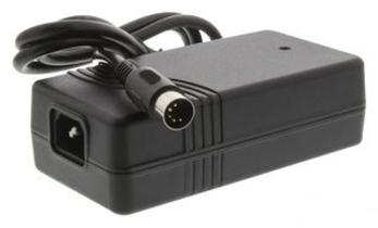

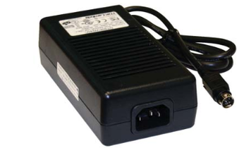
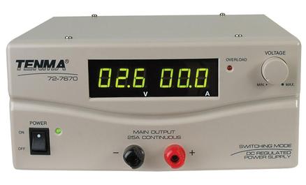


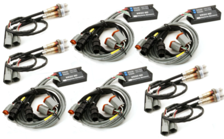
For Eight-Channel dyno installations using Daytona Sensors™ #111003 Four WEGO™ IIID Eight Pack Systems, dyno operators can use the Tenma® Model #72-7670 25 amp power supply available from MCM Electronics® online at www.mcmelectronics.com.
WEGO™ SuperFlow® Interface
Technical Note
NOTE: While we cannot provide tech support for Excel® related software performance issues or help you with individual tuning files, we do however kindly appreciate all comments, suggestions, and feedback about our new approach to data transfer. If you have any feedback regarding this topic, please create a ticket at support.jmschip.com with your opinion and details.
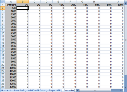
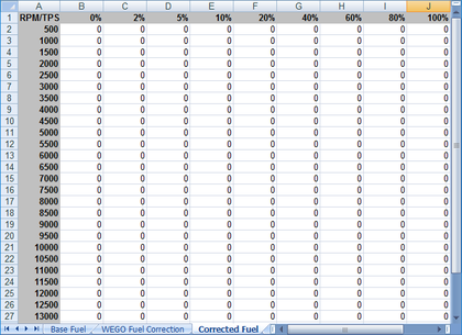
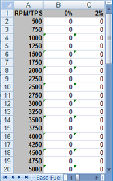
The current product version of WEGO™ software supports all ‘Copy and Paste’ operations. Some of our early versions do not have this functionality. Spreadsheets for use with the WEGO™ system and PC have default filenames containing “WEGO_PC.” The first type (with “AFR” in the filename) has corrections based on WEGO™ AFR data. The second type (with “Fuel” in the filename) is based on WEGO™ fuel percent corrections. Standard spreadsheet table rows are in 500 RPM increments. For PC tuning files that utilize table rows with 250 RPM increments, use the ‘Advanced’ spreadsheets and read the additional notes below. Use the following guidelines to choose between “AFR” or “Fuel” versions:
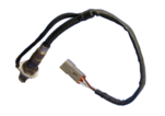
Vehicles operated on a chassis dyno will generate considerable electrostatic charge. The Bosch® LSU 4.2 wide-band exhaust gas oxygen sensor used with the WEGO™ requires a ground connection to the sensor body in order to dissipate electrostatic charge. If the sensor body is not grounded, electrostatic charge will build up until a discharge to the sensor element occurs. This may damage the sensor and input circuitry on the WEGO™ unit.
We recommend grounding the vehicle to the dyno frame while in operation. You can use a length of 16 AWG wire with one end secured to the dyno frame and the other end equipped with a heavy duty alligator clip that is attached to the vehicle frame or other vehicle ground point. The dyno frame or chassis must be connected to building electrical ground in accordance with National Electrical Code (NEC) requirements. Improper grounding will cause serious problems.
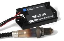
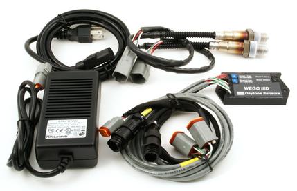
If grounding the vehicle is not convenient, you can use Daytona Sensors Part #115011 grounded sensor, Part #115012 six wire extension cable with ground connection, and Part #115013 ground wire kit for installation at the WEGO™ (see below). Please refer to the Grounded Sensor Tech Note at the right for full details.
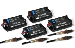
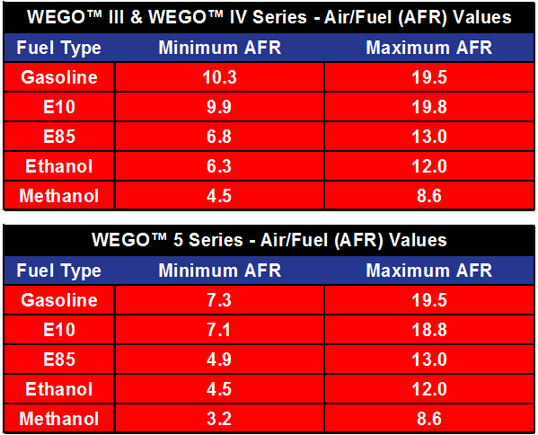
Daytona Sensors™ Dual Channel WEGO™ IIID units are intended for connection to an existing data acquisition system for dyno test lab or professional racing use. These units do not include an LED display or any internal data logging capability. They have 0-5V analog AFR outputs. The analog outputs are linearly scaled with 0V=10.0 AFR and 5V=20.0 AFR (the useful range is 10.3 to 19.5 AFR) and are compatible with industry standard 0-5V analog inputs on most data acquisition systems.
We use cookies to improve your experience on our site. By using our site, you consent to cookies.
Manage your cookie preferences below:
Essential cookies enable basic functions and are necessary for the proper function of the website.
CloudFlare provides web performance and security solutions, enhancing site speed and protecting against threats.
Service URL: developers.cloudflare.com (opens in a new window)
These cookies are needed for adding comments on this website.
Google reCAPTCHA helps protect websites from spam and abuse by verifying user interactions through challenges.
Google Tag Manager simplifies the management of marketing tags on your website without code changes.
WooCommerce is a customizable eCommerce platform for building online stores using WordPress.
Statistics cookies collect information anonymously. This information helps us understand how visitors use our website.
Google Analytics is a powerful tool that tracks and analyzes website traffic for informed marketing decisions.
Service URL: policies.google.com (opens in a new window)
Clarity is a web analytics service that tracks and reports website traffic.
Service URL: clarity.microsoft.com (opens in a new window)
SourceBuster is used by WooCommerce for order attribution based on user source.
Marketing cookies are used to follow visitors to websites. The intention is to show ads that are relevant and engaging to the individual user.
Google Maps is a web mapping service providing satellite imagery, real-time navigation, and location-based information.
Service URL: policies.google.com (opens in a new window)
You can find more information in our Compliance and .